“Control Panels: The Heart of Manufacturing Sites.
Evolution in control panels results in large evolution in production facilities.
And if control panel design, control panel manufacturing processes, and human interaction with them are innovated, control panel manufacturing becomes simpler and takes a leap forward.”
| Rated input voltage |
Rated current | Must operate voltage |
Must release voltage |
Power consumption | Maximum allowable voltage |
|||
|---|---|---|---|---|---|---|---|---|
| AC | DC | Percentage of the rated voltage |
AC (VA) | DC (mW) | Percentage of the rated voltage |
|||
| 50 Hz | 60 Hz | |||||||
| 12 VDC | – | – | 27.9 mA | 80% max.* | 10% min. | – | Approx. 300 mW | 110% |
| 24 VDC | – | – | 13.5 mA | – | Approx. 300 mW | |||
| 24 VAC/VDC | 13.7 mA | 14.9 mA | 12.6 mA | Approx. 0.4 VA | Approx. 300 mW | |||
| 48 VAC/VDC | 5.9 mA | 6.4 mA | 5.4 mA | Approx. 0.3 VA | Approx. 250 mW | |||
| 100 VAC | 6.8 mA | 7.1 mA | – | Approx. 0.7 VA | – | |||
| 110 VAC | 6.1 mA | 6.4 mA | – | Approx. 0.7 VA | – | |||
| 200 VAC | 6.1 mA | 7.3 mA | – | Approx. 1.5 VA | – | |||
| 230 VAC | 6.8 mA | 8.2 mA | – | Approx. 1.9 VA | – | |||
Note: The operating characteristics are measured at ambient temperature of 23°C.
* Operating voltage will be, for mounting in the upside down direction, 85% max.
(Upside down: Direction in which the mechanical indicator faces down)
| Item | Standard (G2RV-ST700, 500, 701, 501) |
For microloads (G2RV-ST700-AP, 500-AP) *2 |
|
|---|---|---|---|
| Contact configuration | SPDT | ||
| Load | Resistive load (cosφ=1) |
Inductive load (cosφ=0.4, L/R=7ms) |
Resistive load (cosφ=1) |
| Rated load | 6 A at 250 VAC 6 A at 30 VDC |
2.5 A at 250 VAC 2 A at 30 VDC |
50 mA at 30 VAC 50 mA at 36 VDC |
| Rated carry current *3 | 6 A | 50 mA | |
| Maximum switching voltage | 440 VAC, 125 VDC | 30 VAC, 36 VDC | |
| Maximum switching current | 6 A | 50 mA | |
| Maximum switching power | 1,500 VA 180 W |
500 VA 60 W |
– |
| Failure rate P value (reference value) *1 |
10 mA at 5 VDC | 1 mA at 100 mVDC | |
*1. P level: λ60=0.1×10⁻⁶/times
This value is the value in switching frequency 120 operations/min.
*2. If the Au plating layer is destroyed, the number will be the same as the standard type.
*3. Please energize under 32A total when use short bar connection.
| Item | Standard (G2RV-ST700, 500, 701, 501) |
For microloads (G2RV-ST700-AP, 500-AP) |
|
|---|---|---|---|
| Contact resistance * | 100 mΩ max. | ||
| Operate time * | 20 ms max. | ||
| Release time * | AC, AC/DC: 40 ms max. DC: 20 ms max. |
||
| Maximum operating frequency | Mechanical: 18,000 operations/h Electrical: 1,800 operations/h (rated load) |
||
| Insulation resistance | 1,000 MΩ min. (at 500 VDC) | ||
| Dielectric strength | Between coil and contacts: 4,000VAC 50/60 Hz 1 min Contact between the same polarity: 1,000 VAC 50/60 Hz 1 min |
||
| Vibration resistance | Destruction: 10 to 55 to 10 Hz, single amplitude 0.50 mm (double amplitude 1.0 mm) Malfunction: 10 to 55 to 10 Hz, single amplitude 0.50 mm (double amplitude 1.0 mm) |
||
| Shock resistance | Destruction: 1,000 m/s2 Malfunction: Energized 200m/s2, Non-energized 100m/s2 |
||
| Endurance * | Mechanical | 5,000,000 operations min. | |
| Electrical | NO contact: 70,000 operations min. NC contact: 50,000 operations min. |
5,000,000 operations min. | |
| Ambient operating temperature |
Operating: -40 to +55°C (with no icing or condensation) | ||
| Ambient operating humidity |
Operating: 5 to 85% RH | ||
| Weight | Approx. 30 g | ||
| Type of interruption | Micro-disconnection | ||
| Type of insulation | Basic isolation: Coil-Contact, Live parts-Ground | ||
| Pollution degree | 2 | ||
| Impulse withstand voltage |
4.0 kV | ||
| Test procedure | A (Group mounting) | ||
| Categories of environmental protection |
RT 1 | ||
| Degree of protection by enclosure according to IEC 60529 |
IP20 | ||
| Contact material | Ag alloy | Ag alloy + Au plating | |
Note: Above values are initial values.
* Value is at ambient temperature of 23°C.
| Model | Contact form | Operation coil ratings | Contact ratings | Operations |
|---|---|---|---|---|
| G2RV-ST series | SPDT | 12 to 48 VDC 24 to 230 VAC |
6 A at 250 VAC (Resistive load) 6 A at 30 VDC (Resistive load) 2 A at 400 VAC (Resistive load)* |
6,000 |
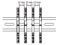
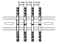
* If the load voltage exceeds 250 VAC, please attach with a spacing of 12 mm min., or use a separate plate (XW5Z-EP12) or 4psc of isolation plate (P2RV-P3.1T).

| Model | Contact form | Operation coil ratings | Contact ratings | Operations |
|---|---|---|---|---|
| G2RV-ST series | SPDT | 12, 24 VDC 24, 48 VAC/VDC 100, 110, 200, 230 VAC |
6 A at 250 VAC (Resistive load) 6 A at 30 VDC (Resistive load) 2 A at 400 VAC (Resistive load)* |
50,000 50,000 6,000 |
* If the load voltage exceeds 250 VAC, please attach with a spacing of 12 mm min., or use a separate plate (XW5Z-EP12) or 4psc of isolation plate (P2RV-P3.1T).

| Rated voltage | 30 VAC/DC | |
|---|---|---|
| Rated current | 0.5 A/poles, 2 A/unit | |
| Ambient operating temperature | -40 to 55°C | |
| Vibration resistance | Destruction | 10 to 55 to 10 Hz, single amplitude 0.50 mm (double amplitude 1.0 mm) |
| Malfunction | 10 to 55 to 10 Hz, single amplitude 0.50 mm (double amplitude 1.0 mm) | |
| Shock resistance | Destruction | 300 m/s2 |
| Malfunction | 100 m/s2 | |