
| Models | H5CX-A[]-N | H5CX-A11[]-N | H5CX-L8[]-N | |
|---|---|---|---|---|
| Classification | Standard Type | Economy Type | ||
| Ratings | Power supply voltage *1 |
100 to 240 VAC 50/60 Hz 12 to 24 VDC/24 VAC 50/60 Hz |
||
| Operating voltage fluctuation range |
85% to 110% of rated supply voltage (90% to 110% at 12 to 24 VDC) | |||
| Power consumption | Approx. 6.2 VA at 100 to 240 VAC, Approx. 5.1 VA/2.4 W at 24 VAC/12 to 24 VDC *2 | |||
| Mounting method | Flush mounting | Flush mounting, surface mounting, DIN track mounting | ||
| External connections | Screw terminals | 11-pin socket | 8-pin socket | |
| Degree of protection | IEC IP66, UL508 Type 4X (indoors) for panel surface only and when Y92S-29 Waterproof Packing is used |
|||
| Digits | 4 digits | |||
| Time ranges | 0.001 s to 9.999 s, 0.01 s to 99.99 s, 0.1 s to 999.9 s, 1 s to 9999 s, 1 s ti 99 min 59 s 0.1 m to 999.9 min, 1 min to 9999 min, 1 min to 99 h 59 min, 0.1 h to 999.9 h, 1 h to 9999 h |
|||
| Timer mode | Elapsed time (Up), remaining time (Down) (selectable) | |||
| Inputs | Input signals | Signal, Reset, Gate | Signal, Reset (no inputs on models with instantaneous contact outputs) |
|
| Input method | No-voltage (NPN) input/ voltage (PNP) input (switchable) No-voltage Input ON impedance: 1 kΩ max. (Leakage current: 12 mA when 0 Ω) ON residual voltage: 3 V max. OFF impedance: 100 kΩ min. Voltage Input High (logic) level: 4.5 to 30 VDC Low (logic) level: 0 to 2 VDC (Input resistance: approx. 4.7 kΩ) |
No-voltage Input ON impedance: 1 kΩ max. (Leakage current: 12 mA when 0 Ω) ON residual voltage: 3 V max. OFF impedance: 100 kΩ min. |
||
| Signal, reset, gate | Minimum input signal width: 1 or 20 ms (selectable, same for all input) | |||
| Reset system | Power reset (depending on output mode), external reset, manual reset, automatic reset (depending on output mode) |
|||
| Power reset | Minimum power-opening time: 0.5 s (except for A-3, b-1, F, ton-1, and toff-1 mode) | |||
| Reset voltage | 10% max. of rated supply voltage | |||
| Sensor waiting time | 250 ms max. (Control output is turned OFF and no input is accepted during sensor waiting time.) |
|||
| Output | Output modes | A: Signal ON Delay I, A-1: Signal ON Delay II, A-2: Power ON Delay I, A-3: Power ON Delay II, b: Repeat Cycle 1, b-1: Repeat Cycle 2, d: Signal OFF Delay, E: Interval, F: Cumulative, Z: ON/OFF-duty-adjustable flicker, S: Stopwatch, toff: Flicker OFF Start 1, ton: Flicker ON Start 1, toff-1: Flicker OFF Start 2, ton-1: Flicker ON Start 2 |
 |
|
| Models with Instantaneous Contact Outputs A-2: Power ON Delay I, b: Repeat Cycle 1, E: Interval, Z: ON/OFF-duty-adjustable flicker, toff: Flicker OFF Start 1, ton: Flicker ON Start 1 |
||||
| One-shot output time |
0.01 to 99.99 s | |||
| Control output | Models with Contact Outputs 5 A at 250 VAC/30 VDC, resistive load (cos =1) Minimum applied load: 10 mA at 5 VDC (failure level: P, reference value) Contact materials: AgSnIn Transistor output: NPN open collector, 100 mA at 30 VDC max., residual voltage: 1.5 VDC max. (Approx. 1 V), Leakage current: 0.1 mA max. |
|||
| Display method *3 | 7-segment, negative transmissive LCD; Present value: 12-mm-high characters, (switchable between red, green, and orange) Set value: 6-mm-high characters, green |
7-segment, negative transmissive LCD; Present value: 12-mm-high characters, red Set value: 6-mm-high characters, green |
||
| Memory backup | EEPROM (overwrites: 100,000 times min.) that can store data for 10 years min. | |||
| Operating temperature range | -10 to 55°C (-10 to 50°C if counters are mounted side by side) (with no icing or condensation) |
|||
| Storage temperature range | -25 to 70°C (with no icing or condensation) | |||
| Operating humidity range | 25% to 85% | |||
| Case color | Black (N1.5) (Optional Front Panels are available to change the Front Panel color to light gray or white.) |
|||
| Attachments | Waterproof packing, flush mounting adapter, label for DIP switch settings |
Label for DIP switch settings |
— | |
| Voltage | Applied voltage | Inrush current (peak value) | Time |
|---|---|---|---|
| 100 to 240 VAC | 264 VAC | 5.3 A | 0.4 ms |
| 12 to 24 VDC/24 VAC | 26.4 VAC | 6.4 A | 1.4 ms |
| 26.4 VDC | 4.4 A | 1.7 ms |
*3. The display is lit only when the power is ON. Nothing is displayed when power is OFF.
| Accuracy of operating time and setting error (including temperature and voltage influences) |
Power-ON start: ±0.01% ±50 ms max. (See note 1.) Signal start: ±0.005%±30 ms max. (See note 1.) Signal start for transistor output model: ±0.005%±3 ms max. (See note 1 and 2.) If the set value is within the sensor waiting time at startup the control output of the H5CX will not turn ON until the sensor waiting time passes. Note: 1. The values are based on the set value. 2. The value is applied for a minimum pulse width of 1 ms. |
|
|---|---|---|
| Insulation resistance | 100 MΩ min. (at 500 VDC) between current-carrying terminal and exposed non-current-carrying metal parts, and between non-continuous contacts | |
| Dielectric strength | 2,000 VAC, 50/60 Hz for 1 min between current-carrying metal parts and non-current-carrying metal parts 2,000 VAC, 50/60 Hz for 1 min between power supply and input circuits for the models other than H5CX-[]D-N and H5CX-L8E[]-N 1,000 VAC, 50/60 Hz for 1 min between control output, power supply, and input circuits (for the models other than H5CX-L8E[]-N) for H5CX-[]SD-N 2,000 VAC, 50/60 Hz for 1 min between control output, power supply, and input circuits (for the models other than H5CX-L8E[]-N) for other models 1,000 VAC, 50/60 Hz for 1 min between non-continuous contacts |
|
| Impulse withstand voltage |
5 kV (between power terminals) for 100 to 240 VAC, 1 kV for 24 VAC/12 to 24 VDC 5 kV (between current-carrying terminal and exposed non-current-carrying metal parts) for 100 to 240 VAC 1.5 kV for 24 VAC/12 to 24 VDC |
|
| Noise immunity | ±1.5 kV (between power terminals) and ±600 V (between input terminals), square-wave noise by noise simulator (pulse width: 100 ns/ 1 μs, 1-ns rise) | |
| Static immunity | Malfunction: 8 kV Destruction: 15 kV |
|
| Vibration resistance |
Destruction | 10 to 55 Hz with 0.75-mm single amplitude each in three directions for 2 h each |
| Malfunction | 10 to 55 Hz with 0.35-mm single amplitude each in three directions for 10 min each | |
| Shock resistance |
Destruction | 300 m/s2 in three directions, three cycles |
| Malfunction | 100 m/s2 in three directions, three cycles | |
| Life expectancy |
Mechanical | 10,000,000 operations min. (under no load at 1,800 operations/h and ambient temperature of 23°C) |
| Electrical | 100,000 operations min. (5 A at 250 VAC, resistive load at 1,800 operations/h and ambient temperature of 23°C) * | |
| Weight | Approx. 115 g (Timer only) | |
* Refer to Life-test Curve.
A maximum current of 0.15 A can be switched at 125 VDC (cosφ =1) and a maximum current of 0.1 A can be switched if L/R is 7 ms. In both cases, a life of 100,000 operations can be expected.
| Approved safety standards | UL508/Listing, UL508 Type 4X for indoor use (enclosure rating), CSA C22.2 No. 14 *1, conforms to EN61812-1 (Pollution degree 2/overvoltage category III) B300 PILOT DUTY 1/4 HP 120 VAC, 1/3 HP, 240 VAC, 5 A resistive load VDE0106/P100 CCC: GB/T 14048.5 Pollution degree 2, Overvoltage category III *2,*3 |
|---|---|
| EMC | (EMI) EN61812-1 Emission Enclosure: EN55011 Group 1 class A Emission AC mains: EN55011 Group 1 class A (EMS) EN61812-1 Immunity ESD: IEC61000-4-2 Immunity RF-interference: IEC61000-4-3 Immunity Burst: IEC61000-4-4 Immunity Surge: IEC61000-4-5 Immunity Conducted Disturbance: IEC61000-4-6 Immunity Voltage Dip/Interruption: IEC61000-4-11 |
| Rated operating voltage Ue Rated operating current Ie |
Contact Output: AC-15: Ue: 250 VAC, Ie: 3 A AC-13: Ue: 250 VAC, Ie: 5 A DC-13: Ue: 30 VDC, Ie: 0.5 A Transistor Output: DC-13: Ue: 30 VDC, Ie: 0.1 A |
|---|---|
| Rated insulation voltage | 250 V |
| Rated impulse withstand voltage (altitude: 2,000 m max.) |
4 kV (at 240 VAC) |
| Conditional short-circuit current |
1000 A |
For details, refer to the timing charts on Data Sheet.
| Inputs *1 |
Start signal | Normally functions to start timing. In modes A-2 and A-3, disable timing. In mode S, starts and stops timing. |
|---|---|---|
| Reset | Resets present value. (In elapsed time mode, the present value returns to 0; in remaining time mode, the present value returns to the set value.) Count inputs are not accepted and control output turns OFF while reset input is ON. Reset indicator is lit while reset input is ON. |
|
| Gate *2 | Disables timing. (If a reset occurs while the gate input is ON, a reset will be performed.) | |
| Outputs | Control output (OUT) |
Outputs take place according to designated operating mode when timer reaches corresponding set value. |
*1. The H5CX-L8E[] does not have an input.
*2. The H5CX-L[] does not have a gate input.
The following table shows the delay from when the reset signal is input until the output is turned OFF.
(Reference value)
| Minimum reset signal width | Output delay time |
|---|---|
| 1 ms | 0.8 to 1.2 ms |
| 20 ms | 15 to 25 ms |
| Classification | Digital Timer with 6-digit display, 2-stage setting, and forecast output | |
|---|---|---|
| Ratings | Power supply voltage | 12 to 24 VDC |
| Operating voltage fluctuation range |
90% to 110% rated supply voltage | |
| Power consumption | Approx. 2.3 W *1 | |
| Mounting method | Flush mounting | |
| External connections | Screw terminals | |
| Degree of protection | IEC IP66, UL508 Type 4X (indoors) for panel front surface only and only when Y92S- 29 Waterproof Packing is used |
|
| Digits | 6 digits | |
| Time range | 0.01 s to 9999.99 s, 1 s to 99 h 59 min 59 s, 0.1 min to 99999.9 min, 0.1 h to 99999.9 h |
|
| Timer mode | Elapsed time (Up) | |
| Inputs | Input signals | Signal, reset, gate |
| Input method | No-voltage (NPN) input/voltage (PNP) input (switchable) No-voltage Input ON impedance: 1 kΩ max. (Leakage current: 12 mA when 0 Ω) ON residual voltage: 3 V max. OFF impedance: 100 kΩ min. Voltage Input High (logic) level: 4.5 to 30 VDC Low (logic) level: 0 to 2 VDC (Input resistance: approx. 4.7 kΩ) |
|
| Signal, reset, gate | Minimum input signal width: 1 or 20 ms (selectable, same for all input) | |
| Reset system | Power resets (only for A mode), external and manual reset | |
| Power reset | Minimum power-opening time: 0.5 s (except for F-1 mode) | |
| Reset voltage | 10% max. of rated supply voltage | |
| Sensor waiting time | 250 ms max. (Control output is turned OFF and no input is accepted during sensor waiting time.) |
|
| Outputs | Output modes | A, F-1 |
| Output type | Transistor output: NPN open collector, 100 mA at 30 VDC max. residual voltage: 1.5 VDC max. (Approx. 1 V) Leakage current: 0.1 mA max. |
|
| Display | 7-segment, negative transmissive LCD; Present value: 10-mm-high characters, red Set value: 6-mm-high characters, green *2 |
|
| Memory backup | EEPROM (overwrites: 100,000 times min.) that can store data for 10 years min. | |
| Operating temperature range | -10 to 55°C (-10 to 50°C if counters are mounted side by side) (with no icing or condensation) |
|
| Storage temperature range | -25 to 70°C (with no icing or condensation) | |
| Operating humidity range | 25 to 85% | |
| Case color | Black (N1.5) | |
| Attachments | Waterproof packing, flush mounting adapter, unit label | |
| Voltage | Applied voltage | Inrush current (peak value) | Time |
|---|---|---|---|
| 12 to 24 VDC | 26.4 VDC | 4.4 A | 1.7 ms |
*2. The display is lit only when the power is ON.
| Accuracy of operating time and setting error (including temperature and voltage influences) |
Power-ON start: ±0.01% ±50 ms max. (See note 1.) Signal start: ±0.005%±0.03 ms max. (See note 1.) Signal start for transistor output model: ±0.005%±3 ms max. (See note 1 and 2.) If the set value is within the sensor waiting time at startup the control output of the H5CX will not turn ON until the sensor waiting time passes. Note: 1. The values are based on the set value. 2. The value is applied for a minimum pulse width of 1 ms. |
|
|---|---|---|
| Insulation resistance | 100 MΩ min. (at 500 VDC) between current-carrying terminal and exposed non-current-carrying metal parts | |
| Dielectric strength | 2,000 VAC, 50/60 Hz for 1 min between current-carrying metal parts and non-current-carrying metal parts 1,000 VAC, 50/60 Hz for 1 min between control output, power supply, and input circuit |
|
| Impulse withstand voltage |
1.0 kV (between power terminals) 1.5 kV (between current-carrying terminal and exposed non-current-carrying metal parts) |
|
| Noise immunity | ±480 V (between power terminals) and ±600 V (between input terminals), square-wave noise by noise simulator (pulse width: 100 ns/1 µs, 1-ns rise) | |
| Static immunity | Destruction: 15 kV Malfunction: 8 kV |
|
| Vibration resistance |
Destruction | 10 to 55 Hz with 0.75-mm single amplitude in three directions for 2 h each |
| Malfunction | 10 to 55 Hz with 0.35-mm single amplitude in three directions for 10 min each | |
| Shock resistance |
Destruction | 300 m/s2 in three directions, three cycles |
| Malfunction | 100m/s2 in three directions, three cycles | |
| Weight | Approx. 105 g (Timer only) | |
| Approved safety standards |
UL508/Listing, CSA C22.2 No. 14, conforms to EN 61812-1 (pollution degree 2/overvoltage category III) Conforms to VDE0106/P100 (finger protection). |
|---|---|
| EMC | (EMI) EN61812-1 Emission Enclosure: EN55011 Group 1 class A (EMS) EN61812-1 Immunity ESD: IEC61000-4-2 Immunity RF-interference: IEC61000-4-3 Immunity Burst: IEC61000-4-4 Immunity Surge: IEC61000-4-5 Immunity Conducted Disturbance: IEC61000-4-6 Immunity Voltage Dip/Interruption: IEC61000-4-11 |
| Inputs | Start signal | Starts timing. | |
|---|---|---|---|
| Reset | Resets present value. (The present value returns to 0.) Timing stops and control output turns OFF while reset input is ON. Reset indicator is lit while reset input is ON. |
||
| Gate | Inhibits timer operation. | ||
| Outputs | Forecast value setting |
Control output (OUT2) | Turns ON when the present value reaches the set value. |
| Forecast output (OUT1) | Turns ON when the present value reaches the forecast value. | ||
| Absolute value setting |
Control output 2 (OUT2) | Turns ON when the present value reaches set value 2. | |
| Control output 1 (OUT1) | Turns ON when the present value reaches set value 1. | ||
The following table shows the delay from when the reset signal is input until the output is turned OFF.
(Reference value)
| Minimum reset signal width | Output delay time |
|---|---|
| 1 ms | 0.8 to 1.2 ms |
| 20 ms | 15 to 25 ms |

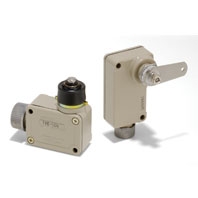
![D4E-[]N](https://enviromiddleeast.com/wp-content/uploads/2022/12/l_330-13-118653-198x198-1.jpg)
![D4A-[]N](https://enviromiddleeast.com/wp-content/uploads/2022/12/l_328-13-118647-198x198-1.jpg)