| Model | Rated time | Time setting range |
|---|---|---|
| H3FA-A | 1 s | 0.1 to 1 s |
| H3FA-AU | 10 s | 1 to 10 s |
| H3FA-SA | 1 min | 0.1 to 1 min |
| H3FA-SAU | 10 min | 1 to 10 min |
| H3FA-B | 6 s | 0.6 to 6 s |
| H3FA-BU | 60 s | 6 to 60 s |
| H3FA-SB | 6 min | 0.6 to 6 min |
| H3FA-SBU | 60 min | 6 to 60 min |
| Item | H3FA-A/ H3FA-B H3FA-AU/ H3FA-BU |
H3FA-SA/ H3FA-SB H3FA-SAU/ H3FA-SBU |
|---|---|---|
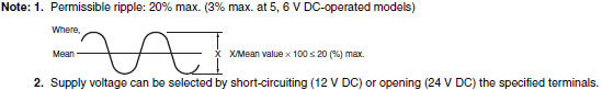
| Rated supply voltage | 5 V DC, 6V DC, 12V DC, 24 V DC *1 | 5/6 V DC *1 12/24 V DC *1, *2 |
| Operating voltage range | 5 V DC: 90% to 110% of rated supply voltage 6, 12, 24 V DC: 85% to 110% of rated supply voltage |
|
| Power consumption | 5, 6 V DC: approx. 230 mW 12 V DC: approx. 270 mW 24 V DC: approx. 330 mW |
5/6 V DC: approx. 80 mW 12 V DC: approx. 100 mW 24 V DC: approx. 240 mW |
| Control outputs | Contact output: SPST-NO + SPST-NC, 3 A at 250 V AC with resistive load, Minimum applied load: 10 mA at 5 V DC (Failure level: P, reference value) |
Solid-state output: 150 mA max. at 30 V DC Residual voltage: 1.0 V max. |
| Ambient temperature | Operating: -10°C to 55°C (with no icing) Storage: -25°C to 65°C (with no icing) |
|
| Ambient humidity | 35% to 85% | |
| Accuracy of operating time |
±0.5% FS max. *1, *3 |
|---|---|
| Setting error | 0 to 30 % FS max. (at 20°C , at rated voltage) |
| Reset time | 10 ms max. |
| Influence of voltage | ±1% FS max. (2% FS max. for 5, 6, 5/6 V DC-operated models) |
| Influence of temperature | ±5% FS max. *1 |
| Insulation resistance | 100 MΩ min. (at 500 V DC) |
| Dielectric strength | 1,500 V AC, 50/60 Hz for 1 min (between control output and operating circuit) *2 1,000 V AC, 50/60 Hz for 1 min (between contacts not located next to each other) *2 |
| Vibration resistance | Destruction: 10 to 55 Hz with 0.375-mm single amplitude in 3 directions for 2 hour each Malfunction: 10 to 55 Hz with 0.25-mm single amplitude in 3 directions for 10 minutes each |
| Shock resistance | Destruction: 1,000 m/s2 3 times each in 6 directions on 3 axes Malfunction: 100 m/s2 3 times each in 6 directions on 3 axes |
| Life expectancy | Mechanical: 10,000,000 operations min. (under no load at 1,800 operations/h) *2 Electrical: 100,000 operations min. (3 A at 250 V AC, resistive load at 1,800 operations/h) *2 |
| Approved safety standards |
UL508, CSA C22.2 No.14 |
| Weight | Contact output models: approx. 15 g Solid-state output models: approx. 10 g |