
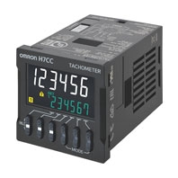
| Classification | Tachometer | |||||
|---|---|---|---|---|---|---|
| Item | H7CC-R11[] | H7CC-R11W[] | ||||
| Input mode | 1 input only | 2 inputs only | ||||
| Ratings | Power supply voltage *1 |
• 100 to 240 VAC, 50/60 Hz • 12 to 24 VDC or 48 VAC, 50/60 Hz |
||||
| Operating voltage fluctuation range |
85% to 110% of rated supply voltage (90% to 110% at 12 to 48 VDC) | |||||
| Power consumption |
Approx. 6.8 VA at 100 to 240 VAC, Approx. 5.5 VA/ 3.3 W at 24 VAC/12 to 48 VDC |
|||||
| Mounting method | Flush mounting or surface mounting | |||||
| External connections | 11-pin socket | |||||
| Degree of protection | IEC IP66 for panel surface only and when Y92S-P6 Waterproof Packing is used | |||||
| Input signals | Count and hold | Count 1 and count 2 | ||||
| Pulse measurement method | Tachometer mode (cycle measurement) | AMD-compatible mode (continuous measurement) |
Tachometer mode (cycle measurement) | |||
| Maximum counting speed | 30 Hz (minimum pulse width: 16.7 ms) |
10 kHz (minimum pulse width: 0.05 ms) |
— | 30 Hz (minimum pulse width: 16.7 ms) or 5 kHz (minimum pulse width: 0.1 ms) (selectable) |
||
| Minimum input signal width | — | 10 ms | 1 ms | — | ||
| Measuring ranges | 0.001 Hz to 30.00Hz | 0.001 Hz to 10 kHz | 0.026 to 999999 s | 0.003 to 999999 s | 0.01 to 5k Hz | |
| Sampling cycle | 200 ms min. | Continuous measurement (minimum interval of 10 ms) |
200 ms min. | |||
| Display refresh cycle | • Input pulse of 5 Hz min. Averaging not used: 200 ms Averaging used: 200 multiplied by the averaging setting (ms) • Input pulse of less than 5 Hz Averaging not used: Two times the maximum input pulse cycle Using averaging: Two times the maximum of the input pulse cycle multiplied by the averaging setting. |
|||||
| Measuring accuracy | ±0.1% FS ±1 digit max. (at 23 ±5°C) | |||||
| Output mode | HI-LO, AREA, HI-HI, LO-LO | HI-HI, LO-LO | ||||
| Auto-zero time | 0.1 to 999.9 s (in Tachometer Mode) | |||||
| Startup time | 0.0 to 99.9 s | |||||
| Averaging | Simple averaging/moving averaging selectable, Number of times: OFF, 2, 4, 8 or 16 times | |||||
| Prescaling function | 0.001 to 99.999 (in Tachometer Mode) | |||||
| Decimal point adjustment | Rightmost 3 digits | — | ||||
| Sensor waiting time | 290 ms max. (Control output is turned OFF and no input is accepted during sensor waiting time.) | |||||
| Input | Input method | No-voltage Input Impedance when ON: 1 kΩ max. (Leakage current: 12 mA when 0 Ω) ON residual voltage: 3 V max. Impedance when OFF: 100 kΩ min. Voltage Input High (logic) level: 4.5 to 30 VDC Low (logic) level: 0 to 2 VDC (Input resistance: approx. 4.7 kΩ) |
||||
| Hold input | Minimum input signal width: 20 ms | — | ||||
| External power supply | 12 VDC (±10%), 100 mA * Refer to Safety Precautions (Common) for details. |
|||||
| Control output | Contact output: 3 A at 250 VAC/30 VDC, resistive load (cosφ=1) Minimum applied load:10 mA at 5 VDC (failure level: P, reference value) |
|||||
| Display *2 | 7-segment, negative transmissive LCD Character height Present value: 10 mm (white), comparison value: 6 mm (green) |
|||||
| Digits | 6 digits (0 to 999999) | |||||
| Memory backup | Non-volatile memory (overwrites: 100,000 times min.) that can store data for 10 years min. | |||||
| Operating temperature range | -10 to 55°C (-10 to 50°C if Counter/Tachometers are mounted side by side) (with no icing or condensation) | |||||
| Storage temperature range | -25 to 70°C (with no icing or condensation) | |||||
| Operating humidity range | 25% to 85% | |||||
| Case color | Black (N1.5) | |||||
*1. Do not use the output from an inverter as the power supply. The ripple must be 20% maximum for CC power.
*2. The display is lit only when the power is ON. Nothing is displayed when power is OFF.
| Insulation resistance | 100 MΩ min. (at 500 VDC) between current-carrying terminal and exposed non-current- carrying metal parts, and between non-continuous contacts |
|
|---|---|---|
| Dielectric strength | 2,000 VAC, 50/60 Hz for 1 min between current-carrying metal parts and non-current-carrying metal parts 2,000 VAC (for 100 to 240 VAC), 50/60 Hz for 1 min between power supply and input circuit (1,500 VAC for 24 VAC/12 to 48 VDC) 2,000 VAC 50/60 Hz for 1 min between control output, power supply, and input circuit 1,000 VAC, 50/60 Hz for 1 min between non-continuous contacts |
|
| Impulse withstand voltage | 6.0 kV (between power terminals) for 100 to 240 VAC, 1.0 kV for 24 VAC/12 to 48 VDC 6.0 kV (between current-carrying terminal and exposed non-current-carrying metal parts) for 100 to 240 VAC, 1.5 kV for 24 VAC/12 to 48 VDC |
|
| Static immunity | Destruction: 15 kV, Malfunction: 8 kV | |
| Vibration resistance |
Destruction | 10 to 55 Hz with 0.75-mm single amplitude, each in three directions for 2 hours |
| Malfunction | 10 to 55 Hz with 0.35-mm single amplitude, each in three directions for 10 min | |
| Shock resistance |
Destruction | 300m/s2 each in three directions, three cycles |
| Malfunction | 100m/s2 each in three directions, three cycles | |
| Life expectancy | Mechanical: 10,000,000 operations min. Electrical: 100,000 operations min. (3 A at 250 VAC, resistive load, ambient temperature condition: 23°C) * |
|
| Weight | Approx. 100 g (Tachometer only) | |
* See Life-test Curve (Reference Values) .
A current of 0.15 A max. can be switched at125 VDC (cosφ=1) (Life expectancy: 100,000operations)
A current of 0.1 A max. can be switched ifL/R=7 ms.
(Life expectancy: 100,000 operations)
| Approved safety standards |
cULus (or cURus): UL508/CSA C22.2 No. 14 *1 Conforms to EN 61010-1 (IEC 61010-1): Pollution degree 2/overvoltage category II, EAC, RCM, B300 PILOT DUTY, 1/4 HP 120 VAC, 1/3 HP, 240 VAC, 3-A, 250 VAC/30 VDC resistive load VDE0106/part100 |
|---|---|
| EMC | (EMI) EN61326-1 *2 Emission Enclosure: EN55011 Group 1 classA Emission AC mains: EN55011 Group 1 classA (EMS) EN61326-1 *2 Immunity ESD: EN61000-4-2: 4 kV contact discharge (level 2); 8 kV air discharge (level 3) Immunity RF-interference: EN61000-4-3: 10 V/m (Amplitude-modulated, 80 MHz to 1 GHz) 3 V/m (Amplitude-modulated, 1.4 G to 2 GHz) 1 V/m (Amplitude-modulated, 2 G to 2.7 GHz) 10 V/m (Pulse-modulated, 900 MHz ±5 MHz) Immunity Conducted Disturbance: EN61000-4-6: 10 V (0.15 to 80 MHz) (level 3) Immunity Burst: EN61000-4-4: 2 kV power-line (level 3); 1 kV I/O signal-line (level 4) Immunity Surge: EN61000-4-5: 1 kV line to lines (power and output lines) (level 2); 2 kV line to ground (power and output lines) (level 3) Immunity Voltage Dip/Interruption: EN61000-4-11: Voltage Dip 1 cycle, 100%(rated voltage) 10/12 cycle, 60%(rated voltage) 25/30 cycle, 30%(rated voltage) Interruption 250/300 cycle, 100%(rated voltage) |
*1. The following safety standards apply to the H7CC-R11[].
cUL (Listing): Applicable when an OMRON P2CF(-E) Socket is used.
cUR (Recognition): Applicable when any other socket is used.
*2. Industrial electromagnetic environment (EN/IEC 61326-1 Table 2)
| Inputs | Count, count 1, count 2 |
Reads counting signals. |
|---|---|---|
| Hold | • Holds the measurement value and outputs. • The hold indicator is lit during hold. * |
|
| Outputs | OUT, OUT1, OUT2 | Outputs signals according to the specified output mode when a comparison value is reached. |

![D4A-[]N](https://enviromiddleeast.com/wp-content/uploads/2022/12/l_328-13-118647-198x198-1.jpg)
![Floatless Level Switch (Plug-in Type) 61F-G[]P](https://enviromiddleeast.com/wp-content/uploads/2022/12/l_246-13-118525-198x198-1.jpg)