| Power supply voltage | No D in model number: 100 to 240 VAC, 50/60 Hz D in model number: 24 VAC, 50/60 Hz; 24 VDC |
|
|---|---|---|
| Operating voltage range | 85% to 110% of rated supply voltage | |
| Power consumption | 100 to 240 VAC: 8.5 VA (max.) (E5CN-HTR2 at 100 VAC: 3.0 VA) 24 VAC/VDC: 5.5 VA (24 VAC)/3.5 W (24 VDC) (max.) (E5CN-HTR2D at 24 VAC: 2.7 VA) |
|
| Sensor input | Any of the following can be selected (i.e., fully universal input). Thermocouple: K, J, T, E, L, U, N, R, S, B, W, or PL II Platinum resistance thermometer: Pt100 or JPt100 Current input: 4 to 20 mA or 0 to 20 mA Voltage input: 1 to 5 V, 0 to 5 V, or 0 to 10 V |
|
| Input impedance | Current input: 150 Ω max., Voltage input: 1 MΩ min. (Use a 1:1 connection when connecting the ES2-HB-N.) |
|
| Control method | ON/OFF control or 2-PID control (with auto-tuning) | |
| Control output |
Relay output | SPST-NO, 250 VAC, 3 A (resistive load), electrical life: 100,000 operations, minimum applicable load: 5 V, 10 mA |
| Current output | 4 to 20 mA DC/0 to 20 mA DC, load: 600 Ω max., resolution: approx. 10,000 * | |
| Linear voltage output |
0 to 10 VDC (load: 1 kΩ min.), Resolution: Approx. 10,000 | |
| Auxiliary output |
Number of outputs | 2 max. |
| Output specifications |
Relay output: SPST-NO, 250 VAC, 3 A (resistive load), electrical life: 100,000 operations, minimum applicable load: 5 V, 10 mA |
|
| Event input |
Number of outputs | 2 |
| External contact input specifications |
Contact input: ON: 1 kΩ max., OFF: 100 kΩ min. | |
| Non-contact input: ON: Residual voltage: 1.5 V max., OFF: Leakage current: 0.1 mA max. |
||
| Current flow: Approx. 7 mA per contact | ||
| Logic operations |
Number of operations |
8 max. (Combinations can be made using work bits.) |
| Operations | Logic operation: Any of the following four patterns can be selected. The input status may be inverted. (A and B) or (C and D), (A or C) and (B or D), A or B or C or D, A and B and C and D (A, B, C, and D are four inputs.) Delay: ON delay or OFF delay for the results of the logic operation given above. Setting time: 0 to 9999 s or 0 to 9999 min Output inversion: Possible |
|
| Outputs | One work bit per operation | |
| Work bit assignments |
Any of the following can be assigned to up to eight work bits (logic operation results): Operation commands (assigned to event inputs) *, auxiliary outputs, or control outputs. * Application is possible with models that do not have event inputs by using an internal assignment. |
|
| Transfer outputs |
Number of outputs | 1 max. |
| Output specifications |
Current output: 4 to 20 mA DC, Load: 600 Ω max., Resolution at 4 to 20 mA: Approx. 10,000 |
|
| RSP input | Not supported | |
| Setting method | Digital setting using front panel keys | |
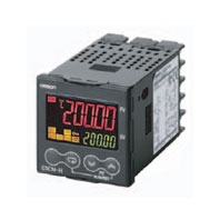
| Indication method | 11-segment digital display and individual indicators (7-segments displays also possible) Character height: PV: 11 mm, SV: 6.5 mm |
|
| Other functions | Manual output, heating/cooling control, loop burnout alarm, other alarm functions, heater burnout detection (including SSR failure and heater overcurrent detection), 40% AT, 100% AT, MV limiter, input digital filter, temperature input shift, run/reset, protection functions, control output ON/OFF counter, extraction of square root, MV change rate limit, PV/SV status display, automatic cooling coefficient adjustment, program control functions, etc. |
|
| Ambient operating temperature | -10 to 55 °C (with no condensation or icing), for 3-year warranty: -10 to 50 °C | |
| Ambient operating humidity | 25% to 85% | |
| Storage temperature | -25 to 65 °C (with no condensation or icing) | |
* For models with current outputs, control output 1 can be used as a transfer output.
Shaded settings are the default settings.
The applicable standards for the input types are as follows:
K, J, T, E, N, R, S, B: JIS C 1602-1995, IEC 584-1
L: Fe-CuNi, DIN 43710-1985
U: Cu-CuNi, DIN 43710-1985
W: W5Re/W26Re, ASTM E988-1990
JPt100: JIS C 1604-1989, JIS C 1606-1989
Pt100: JIS C 1604-1997, IEC 751
PL II: According to Platinel II electromotive force charts from BASF (previously Engelhard)
Each alarm can be independently set to one of the following 13 alarm types. The default is 2: Upper limit.
Auxiliary outputs are allocated for alarms. ON delays and OFF delays (0 to 999 s) can also be specified.
Note: For models with heater burnout, SSR failure, and heater overcurrent detection, alarm 1 will be an OR output of the
alarm selected from the following alarm types and the alarms for heater burnout, SSR failure, and heater
overcurrent. To output only a heater burnout alarm, SSR failure alarm, and heater overcurrent alarm for alarm 1,
set the alarm type to 0 (i.e., no alarm function).
| Set value |
Alarm type | Alarm output operation | Description of function | |
|---|---|---|---|---|
| When alarm value X is positive |
When alarm value X is negative |
|||
| 0 | Alarm function OFF | Output OFF | No alarm | |
| 1 *1 | Upper- and lower-limit |
 |
*2 | Set the deviation in the set point by setting the alarm upper limit (H) and alarm lower limit (L). |
| 2 | Upper-limit |
 |
 |
Set the upward deviation in the set point by setting the alarm value (X). |
| 3 | Lower-limit |
 |
 |
Set the downward deviation in the set point by setting the alarm value (X). |
| 4 *1 | Upper- and lower-limit range |
 |
*3 | Set the deviation in the set point by setting the alarm upper limit (H) and alarm lower limit (L). |
| 5 *1 | Upper- and lower-limit with standby sequence |
|
*4 | A standby sequence is added to the upper- and lower-limit alarm (1). *6 |
| 6 | Upper-limit with standby sequence |
|
|
A standby sequence is added to the upper-limit alarm (2). *6 |
| 7 | Lower-limit with standby sequence |
|
|
A standby sequence is added to the lower-limit alarm (3). *6 |
| 8 | Absolute-value upper-limit |
 |
 |
The alarm will turn ON if the process value is larger than the alarm value (X) regardless of the set point. |
| 9 | Absolute-value lower-limit |
 |
 |
The alarm will turn ON if the process value is smaller than the alarm value (X) regardless of the set point. |
| 10 | Absolute-value upper-limit with standby sequence |
|
|
A standby sequence is added to the absolute-value upper-limit alarm (8). *6 |
| 11 | Absolute-value lower-limit with standby sequence |
|
|
A standby sequence is added to the absolute-value lower-limit alarm (9). *6 |
| 12 | LBA (alarm 1 type only) | — | *7 | |
| 13 | PV change rate alarm | — | *8 | |


| Indication accuracy | Thermocouple: (± 0.1% of indicated value or ± 1 °C, whichever is greater) ± 1 digit max. *1 Platinum resistance thermometer: (± 0.1% of indicated value or ± 0.5 °C, whichever is greater) ± 1 digit max. Analog input: ± 0.1% FS ± 1 digit max. CT input: ± 5% FS ± 1 digit max. |
|
|---|---|---|
| Transfer output accuracy | ± 0.3% FS max. | |
| Influence of temperature *2 |
Thermocouple input (R, S, B, W, PLII): (± 1% of PV or ± 10 °C, whichever is greater) ± 1 digit max. Other thermocouple input: (± 1% of PV or ± 4 °C, whichever is greater) ± 1 digit max. *3 Platinum resistance thermometer: (± 1% of PV or ± 2 °C, whichever is greater) ± 1 digit max. Analog input: (± 1%FS) ± 1 digit max. |
|
| Influence of voltage *2 | ||
| Influence of EMS. (at EN 61326-1) |
||
| Input sampling period | 60 ms | |
| Hysteresis | Temperature input: 0.1 to 3240.0 °C or °F (in units of 0.1 °C or °F) Analog input: 0.01% to 99.99% FS (in units of 0.01% FS) |
|
| Proportional band (P) | Temperature input: 0.1 to 3240.0 °C or °F (in units of 0.1 °C or °F) Analog input: 0.1% to 999.9% FS (in units of 0.1% FS) |
|
| Integral time (I) | 0.0 to 3240.0 s (in units of 0.1 s) | |
| Derivative time (D) | 0.0 to 3240.0 s (in units of 0.1 s) | |
| Control period | 0.5, 1 to 99 s (in units of 1 s) | |
| Manual reset value | 0.0 to 100.0% (in units of 0.1%) | |
| Alarm setting range | -19999 to 32400 (decimal point position depends on input type) | |
| Affect of signal source resistance |
Thermocouple: 0.1°C/Ω max. (100 Ω max.) Platinum resistance thermometer: 0.1°C/Ω max. (10 Ω max.) |
|
| Insulation resistance | 20 MΩ min. (at 500 VDC) | |
| Dielectric strength | 2,300 VAC, 50 or 60 Hz for 1 min (between terminals with different charge) | |
| Vibration resistance |
Malfunction | 10 to 55 Hz, 20 m/s2 for 10 min each in X, Y, and Z directions |
| Destruction | 10 to 55 Hz, 0.75-mm single amplitude for 2 hrs each in X, Y, and Z directions | |
| Shock resistance |
Malfunction | 100 m/s2, 3 times each in X, Y, and Z directions |
| Destruction | 300 m/s2, 3 times each in X, Y, and Z directions | |
| Weight | Controller: Approx. 150 g, Mounting Bracket: Approx. 10 g | |
| Degree of protection | Front panel: IP66, Rear case: IP20, Terminals: IP00 | |
| Memory protection | Non-volatile memory (number of writes: 1,000,000 times) | |
| Setup Tool | CX-Thermo version 4.3 or higher | |
| Setup Tool port | Provided on the bottom of the E5CN-HT. Use this port to connect a computer to the E5CN-HT. An E58-CIFQ1 USB-Serial Conversion Cable is required to connect the computer to the E5CN-HT. *4 |
|
| Standards | Approved standards |
UL 61010-1, CSA C22.2 No. 1010-1 |
| Conformed standards |
EN 61010-1 (IEC 61010-1): Pollution level 2, overcurrent category II | |
| EMC | EMI: EN 61326-1 *5 Radiated Interference Electromagnetic Field Strength: EN 55011 Group 1, class A Noise Terminal Voltage: EN 55011 Group 1, class A EMS: EN 61326-1 *5 ESD Immunity: EN 61000-4-2 Electromagnetic Field Immunity: EN 61000-4-3 Burst Noise Immunity: EN 61000-4-4 Conducted Disturbance Immunity: EN 61000-4-6 Surge Immunity: EN 61000-4-5 Power Frequency Magnetic Field Immunity: EN 61000-4-8 Voltage Dip/Interrupting Immunity: EN 61000-4-11 |
|
*1. The indication accuracy of K thermocouples in the -200 to 1300°C range, T and N thermocouples at a temperature of
-100°C max., and U and L thermocouples at any temperatures is ±2°C ±1 digit max. The indication accuracy of the
B thermocouple at a temperature of 400°C max. is not specified. The indication accuracy of B thermocouples in the
400 to 800°C range is ±3°C max. The indication accuracy of the R and S thermocouples at a temperature of 200°C
max. is ±3°C ±1 digit max. The indication accuracy of W thermocouples is ±0.3 of PV or ±3°C, whichever is greater,
±1 digit max. The indication accuracy of PL II thermocouples is ±0.3 of PV or ±2°C, whichever is greater, ±1 digit
max.
*2. Ambient temperature: -10°C to 23°C to 55°C, Voltage range: -15% to 10% of rated voltage
*3. K thermocouple at -100°C max.: ±10°C max.
*4. External communications (RS-232C or RS-485) and cable communications for the Setup Tool can be used at the
same time.
*5. Industrial electromagnetic environment (EN/IEC 61326-1 Table 2)
| Number of programs (patterns) | 8 | |
|---|---|---|
| Number of segments (steps) | 32 | |
| Segment setting method | Time setting (Segment set with set point and time.) | |
| Gradient setting (Segment type with set point, gradient, and time.) | ||
| Segment times | 0 h 0 min to 99 h 59 min | |
| 0 min 0 s to 99 min 59 s | ||
| Alarm setting | Set separately for each program. | |
| Reset operation | Select either stopping control or fixed SP operation. | |
| Startup operation | Select continuing, resetting, manual operation, or run mode. | |
| PID sets | Number of sets | 8 |
| Setting method | Set separately for each program (automatic PID group selection also supported). |
|
| Alarm SP function | Select from ramp SP and target SP. | |
| Program status control | Segment operation | Advance, hold |
| Program operation | Program repetitions and program links | |
| Wait operation | Wait method | Waiting at segment ends |
| Wait width setting | Same wait width setting for all programs | |
| Time signals | Number of outputs | 2 |
| Number of ON/OFF Operations | 1 each per output | |
| Setting method | Set separately for each program. | |
| Program status output | Program end output (pulse width can be set), run output, stage output | |
| Program startup operation | PV start | Select from segment 1 set point, slope-priority PV start |
| Standby | 0 h 0 min to 99 h 59 min | |
| 0 day 0 h to 99 day 23h | ||
| Operation end operation | Select from resetting, continuing control at final set point, and fixed SP control. | |
| Program SP shift | Same program SP shift for all programs | |
| Applicable OS | Windows XP/Vista/7/8/8.1/10 |
|---|---|
| Applicable software | CX-Thermo version 4 or higher |
| Applicable models | E5AN/E5EN/E5CN/E5CN-U/E5AN-H/E5EN-H/E5CN-H/E5ANHT/E5EN-HT/ E5CN-HT |
| USB interface standard | Conforms to USB Specification 1.1. |
| DTE speed | 38400 bps |
| Connector specifications | Computer: USB (type A plug) Temperature Controller: Setup Tool port (on bottom of Controller) |
| Power supply | Bus power (Supplied from USB host controller.) |
| Power supply voltage | 5 VDC |
| Current consumption | 70 mA |
| Ambient operating temperature | 0 to 55°C (with no condensation or icing) |
| Ambient operating humidity | 10% to 80% |
| Storage temperature | – 20 to 60°C (with no condensation or icing) |
| Storage humidity | 10% to 80% |
| Altitude | 2,000 m max. |
| Weight | Approx. 100 g |
Note: A driver must be installed in the personal computer. Refer to installation information in the operation manual for
the Conversion Cable.
| Transmission line connection method | RS-485: Multipoint RS-232C: Point-to-point |
|---|---|
| Communications | RS-485 (two-wire, half duplex)/RS-232C |
| Synchronization method | Start-stop synchronization |
| Protocol | CompoWay/F or Modbus |
| Baud rate | 1200, 2400, 4800, 9600, 19200, 38400, or 57600 bps |
| Transmission code | ASCII (CompoWay/F, SYSWAY) RTU (Modbus) |
| Data bit length * | 7 or 8 bits |
| Stop bit length * | 1 or 2 bits |
| Error detection | Vertical parity (none, even, odd) Block check character (BCC) with CompoWay/F or CRC-16 Modbus |
| Flow control | None |
| Interface | RS-485, RS-232C |
| Retry function | None |
| Communications buffer | 217 bytes |
| Communications response wait time | 0 to 99 ms Default: 20 ms |
* The baud rate, data bit length, stop bit length, and vertical parity can be individually set using the Communications
Setting Level.
| Dielectric strength | 1,000 VAC for 1 min |
|---|---|
| Vibration resistance | 50 Hz, 98 m/s2 |
| Weight | E54-CT1: Approx. 11.5 g, E54-CT3: Approx. 50 g |
| Accessories (E54-CT3 only) | Armatures (2) Plugs (2) |
| CT input (for heater current detection) | Models with detection for single-phase heaters: One input Models with detection for single-phase or three-phase heaters: Two inputs |
|---|---|
| Maximum heater current | 50 A AC |
| Input current indication accuracy | ±5% FS ±1 digit max. |
| Heater burnout alarm setting range *1 | 0.1 to 49.9 A (in units of 0.1 A) Minimum detection ON time: 100 ms |
| SSR failure alarm setting range *2 | 0.1 to 49.9 A (in units of 0.1 A) Minimum detection OFF time: 100 ms |
| Heater overcurrent alarm setting range *3 | 0.1 to 49.9 A (in units of 0.1 A) Minimum detection ON time: 100 ms |