

| Power supply voltage | 100 to 240 VAC 50/60 Hz, 24 VAC 50/60 Hz, or 24 VDC | |
|---|---|---|
| Operating voltage range | 85% to 110% of rated supply voltage | |
| Power consumption | Approx. 3.5 VA (100 to 240 VAC) Approx. 3.5 VA (24 VAC) Approx. 2.5 W (24 VDC) |
|
| Sensor input | Models with thermocouple inputs Thermocouple: K, J, T, R, or S (JIS C 1602-1995, IEC60584-1) Models with platinum resistance thermometer inputs Platinum resistance thermometer: Pt100 (JIS C 1604-1997, IEC60751) |
|
| Control output |
Relay output | SPST-NO, 250 VAC, 3 A (resistive load), electrical life: 100,000 operations, minimum applicable load: 5 V, 10 mA |
| Voltage output (for driving SSR) |
Output voltage: 12 VDC +25%/-15% (PNP), max. load current: 21 mA, with short-circuit protection circuit |
|
| Alarm output |
Relay output | SPST-NO, 250 VAC, 1 A (resistive load), electrical life: 100,000 operations, minimum load: 5 V, 10 mA |
| Control method | ON/OFF control or 2-PID control (with auto-tuning) | |
| Setting method | Digital setting using front panel keys | |
| Indication method | 7-segment digital display and individual indicators Character height: 16.2 mm (PV) |
|
| Other functions | Temperature input shift, run/stop, protection functions, etc. | |
| Ambient operating temperature |
-10 to 55°C (with no condensation or icing)/With a three-year guarantee: -10 to 50°C | |
| Ambient operating humidity | 25% to 85% | |
| Storage temperature | -25 to 65°C (with no condensation or icing) | |
| Model (temperature input) |
Set value | Input type | Range | |
|---|---|---|---|---|
| °C | °F | |||
| TC input | 0 | K | -200 to 1,300 | -300 to 2,300 |
| 1 | -20.0 to 500.0 | 0.0 to 900.0 | ||
| 2 | J | -100 to 850 | -100 to 1500 | |
| 3 | -20.0 to 400.0 | 0.0 to 750.0 | ||
| 4 | T | -200 to 400 | -300 to 700 | |
| 5 | -199.9 to 400.0 | -199.9 to 700.0 | ||
| 6 | R | 0 to 1,700 | 0 to 3,000 | |
| 7 | S | 0 to 1,700 | 0 to 3,000 | |
Default setting: 0
Applicable standards (K, J, T, R, S): JIS C1602-1995 and IEC 60584-1
| Model (temperature input) |
Set value | Input type | Range | |
|---|---|---|---|---|
| °C | °F | |||
| Pt input | 8 | Pt100 | -200 to 850 | -300 to 1500 |
| 9 | -199.9 to 500.0 | -199.9 to 900.0 | ||
Default setting: 8
Applicable standards (Pt100): JIS C1604-1997 and IEC 60751
Select alarm types out of the 11 alarm types listed in the following table.
| Setting | Alarm type | Positive alarm value (X) |
Negative alarm value (X) |
Deviation alarm/ absolute value alarm |
|---|---|---|---|---|
| 0 | No alarm | Output OFF | ||
| 1 | Upper/lower limit |
 |
Always ON | Deviation alarm |
| 2 | Upper limit |
 |
 |
Deviation alarm |
| 3 | Lower limit |
 |
 |
Deviation alarm |
| 4 | Upper/lower range |
 |
Always OFF | Deviation alarm |
| 5 *2 | Upper/lower limit standby sequence ON |
|
Always OFF | Deviation alarm |
| 6 *2 | Upper limit standby sequence ON |
|
|
Deviation alarm |
| 7 *2 | Lower limit standby sequence ON |
|
|
Deviation alarm |
| 8 | Absolute value upper limit |
 |
 |
Absolute value alarm |
| 9 | Absolute value lower limit |
 |
 |
Absolute value alarm |
| 10 *2 | Absolute value upper limit standby sequence ON |
|
|
Absolute value alarm |
| 11 *2 | Absolute value lower limit standby sequence ON |
|
|
Absolute value alarm |
| 12 | Do not set. | |||
Example: Deviation Lower Limit Standby Sequence ON
The standby sequence is cleared when the alarm OFF condition has been met.
The standby sequence is started again when any of the following conditions is met.
• Operation is started (power is turned ON or operation is switched from stop to run).
• The alarm value is changed.
• The temperature input offset is changed.
• The set point is changed.
| Indication accuracy | Thermocouple: (See note 1.) (±0.5% of indicated value or ±1°C, whichever is greater) ±1 digit max. Platinum resistance thermometer: (±0.5% of indicated value or ±1°C, whichever is greater) ±1 digit max. |
|
|---|---|---|
| Influence of temperature (See note 2.) |
R and S thermocouple inputs: (±1% of PV or ±10°C, whichever is greater) ±1 digit max. K, J, and T thermocouple inputs: (±1% of PV or ±4°C, whichever is greater) ±1 digit max. Platinum resistance thermometer inputs: (±1% of PV or ±2°C, whichever is greater) ±1 digit max. |
|
| Influence of voltage (See note 2.) |
||
| Influence of EMS. (at EN 61326-1) |
||
| Hysteresis | 0.1 to 999.9 (in units of 0.1) °C/°F | |
| Proportional band (P) | 0.1 to 999.9 (in units of 0.1) °C/°F | |
| Integral time (I) | 0 to 3999 s (in units of 1 s) | |
| Derivative time (D) | 0 to 3999 s (in units of 1 s) | |
| Control period | 0.5, 1 to 99 s (in units of 1 s) | |
| Alarm setting range | -1999 to 9999 (decimal point position depends on input type) | |
| Input sampling period | 250 ms | |
| Affect of signal source resistance | Thermocouple: 0.1°C/Ω max. (100 Ω max.) (See note 3.) Platinum resistance thermometer: 0.6°C/Ω max. (10 Ω max.) |
|
| Insulation resistance | 20 MΩ min. (at 500 VDC) | |
| Dielectric strength | 2,800 VAC, 50 or 60 Hz for 1 min (between terminals with different charge) | |
| Vibration resistance |
Malfunction | 10 to 55 Hz, 20 m/s2 for 10 min each in X, Y, and Z directions |
| Destruction | 10 to 55 Hz, 20 m/s2 for 2 hrs each in X, Y, and Z directions | |
| Shock resistance |
Malfunction | 200 m/s2, 3 times each in X, Y, and Z directions |
| Destruction | 300 m/s2, 3 times each in X, Y, and Z directions | |
| Weight | Controller: Approx. 100 g, Mounting Bracket: Approx. 10 g | |
| Degree of protection | Front panel: IP66 Rear case: IP20, Terminals: IP00 |
|
| Memory protection | Non-volatile memory (number of writes: 100,000 times) | |
| Conformed standards |
Certified standards | UL 61010-1, CSA C22.2 No. 1010-1 |
| Applicable standards | EN61326, EN61010-1, IEC61010-1 VDE0106, Part 100 (Finger protection), when the terminal cover is mounted. |
|
| EMC | EMI EN61326-1 (See note 4.) Emission Enclosure: EN55011 Group1 Class A Emission AC Mains: EN55011 Group1 Class A EMS EN61326-1 (See note 4.) Immunity ESD: EN61000-4-2 Immunity RF-interference: EN61000-4-3 Immunity Burst: EN61000-4-4 Conduction Disturbance Immunity EN61000-4-6 Immunity Surge: EN61000-4-5 Immunity Voltage Dip/Interrupting: EN61000-4-11 |
|
Note: 1. The indication accuracy of K and T thermocouples at a temperature of −100°C max. is ±2°C ±1 digit maximum.
The indication accuracy of the R and S thermocouples at a temperature of 200°C max. is ±3°C ±1 digit max.
2. Conditions: Ambient temperature: −10 to 23 to 55°C, Voltage range: −15% to ±10% of rated voltage
3. R, and S sensors: 0.2°C/Ω max. (100 Ω max.)
4. Industrial electromagnetic environment (EN/IEC 61326-1 Table 2)
| Applicable OS | Windows XP/Vista/7/8/8.1/10 |
|---|---|
| Applicable software | Thermo Mini |
| Applicable models | E5CB Series |
| USB interface standard | USB specification 1.1 |
| DTE speed | 38,400 bps |
| Connector Specifications | Computer: USB (Type A plug) Temperature Controller: Special serial connector |
| Power supply | Bus power (supplied from the USB host controller) |
| Power supply voltage | 5 VDC |
| Current consumption | 450 mA max. |
| Output voltage | 4.7±0.2 VDC (Supplied from USB-Serial Conversion Cable to the Temperature Controller.) |
| Output current | 250 mA max. (Supplied from USB-Serial Conversion Cable to the Temperature Controller.) |
| Ambient temperature | 0 to 55°C (with no condensation or icing) |
| Ambient humidity | 10% to 80% |
| Storage temperature | -20 to 60°C (with no condensation or icing) |
| Storage humidity | 10% to 80% |
| Altitude | 2,000 m max. |
| Weight | Approx. 120 g |
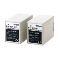
![Floatless Level Switch (Plug-in Type) 61F-G[]P](https://enviromiddleeast.com/wp-content/uploads/2022/12/l_246-13-118525-198x198-1.jpg)
![Floatless Level Switch (Compact Type) 61F-G[]N](https://enviromiddleeast.com/wp-content/uploads/2022/12/l_243-13-118524-198x198-1.jpg)